Fault Tree Analysis: How to do it
The Quality Toolbook >
Fault Tree Analysis > How to do it
When to use it | How to understand it |
Example | How to do it | Practical
variations
<-- Previous |
Next -->
How to do it
- Identify the failure effect to be analyzed. Typically this will be a critical effect that must be eliminated or reduced. It should be a complex failure, which may be caused by combinations of other failures, rather than a low-level failure with simple causes.
This may be found using other tools, such as Failure Mode and Effects Analysis.
- Write the failure effect in a box at the top-center of the diagram area. Make this a clear phrase that describes the effect as precisely as possible, describing not only what the failure is, but how it occurs. For example, 'carburetor fails when engine reaches full temperature'.
- List failures that may directly contribute to the failure described in step 2. For example, 'fuel delivery failure', 'air intake blockage', etc.
When identifying ways in which an item may fail, try looking at the problem from different angles. For example:
- Excessive stresses and strains.
- Potential misuse and abuse.
- Environmental extremes.
- Natural variation in the system.
- Failure of dependent systems.
- Failure of related processes.
- Divide the list of failures in the list derived in step 3 into separate groups, where all members of each group must occur together for the failure in step 2 to occur. For example, 'dirt in fuel' and 'partially blocked jet'. There are three possible outcomes from this:
- There is one group, as all failures identified in step 3 must occur together for the failure from step 2 to happen. This is an 'and' group, so draw an 'and' gate under the failure from step 2 and connect this to boxes underneath containing the failures from step 3, as in
(a) in the illustration below.
- No such groups can be found as any one failure from step 3 can result in the failure effect from step 2. This is an 'or' group, so draw an 'or' gate under the failure from step 2 and connect this to boxes underneath containing the failures from step 3, as
shown in (b) in the illustration below.
- There are several groups. This is a complex grouping, so draw each group with more than one member under an 'and' gate and connect these gates to an 'or' gate under the failure effect from step 2, as shown in (c) in the
illustration below.
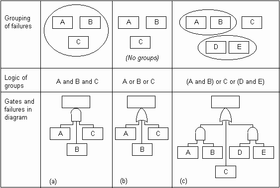
Fig. 1. Grouping failures under gates
It may also be worth checking whether any 'and' group
actually constitutes an independent failure effect. This can be shown with an
additional failure box above the 'and' gate.
There may also be additional conditions for a failure or group of failures to
occur. For example, environmental or procedural conditions such as 'ambient
temperature >50° C' or 'engine idling'. These may be shown with an inhibit gate,
as in Fig. 2.
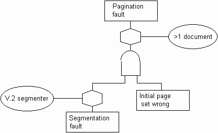
Fig. 2. Adding inhibit gate
- For each failure which has no connections below it, decide whether or not to develop this further by finding other failures which may contribute to it. If the failure is not to be developed on this diagram, draw it in an appropriate box. Thus, if the failure cannot reasonably be developed further, put it in a circle; if it could be developed, but is not appropriate to do this here, then use a diamond-shaped box. If the failure is to be developed, repeat step 3 to find contributory failures and appropriate gates.
- When the diagram is complete, examine it to draw conclusions and plan for appropriate actions. For example, acting to reduce risks such as critical failures and safety hazards.
<-- Previous |
Next -->
|